|Articles|June 29, 2023
Image Analysis Algorithm for Therapeutic mAb Aggregate Analysis
Author(s)Anurag S. Rathore, Shravan Sreenivasan
Image analysis algorithms coupled with microscopy techniques can be used to characterize aggregates of therapeutic proteins.
Advertisement
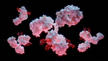
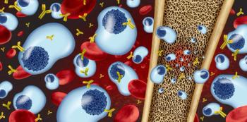
Monoclonal antibodies (mAbs) are an important class of therapeutic proteins used for treating various diseases such as cancers, autoimmune diseases, and genetic disorders (1,2). Therapeutic mAb products are known to have different variants, such as conformational isomers, charge variants, glycan variants, and size variants (3). Size variants, such as aggregates and fragments, are formed when samples containing mAbs undergo stresses, such as those encountered during the various stages of the product life cycle, including cell culture, purification, storage, formulation, transportation, administration, and handling. The formation of aggregates as the result of various stress factors can lead to the reduction of process yield and product shelf life. The administration of samples containing mAb aggregates to patients may also result in adverse immune responses such as anaphylaxis and neutralization of endogenous proteins. Hence, monitoring, analysis, and control of mAb stability is a critical challenge, and researchers and manufacturers continue to show interest in it as well (3–5).
Characterizing IgG aggregates
Monoclonal antibody aggregation is influenced by a variety of factors, such as buffer composition, ionic strength, protein concentration, mechanical stress, temperature, interfacial surfaces, and chemical contaminants. Aggregates could vary in size, structure, and morphology (2). They can be soluble oligomers (less than 100 nm size) or particles of sub-visible (0.1–100 µm) and visible (more than 100 µm) size range (6). Therapeutic protein aggregates of different size ranges are analyzed using an array of techniques such as size exclusion chromatography (SEC), dynamic lightscattering (DLS), asymmetricalflow field-flow fractionation, electrophoresis, analytical ultracentrifugation, light obscuration,nanoparticle tracking analysis, microscopes, and flow-based imaging techniques (7,8). Microscopes and flow-based imaging techniques are widely used and play a crucial role in aggregate analysis. The application of different microscopes to analyze aggregates of mAb has also been mentioned in the European Pharmacopoeia and by FDA (8).
Microscopy and image analysis algorithm
Optical, electron, and atomic force microscopy are among the commonly used microscopes to visualize aggregates of therapeutic proteins (8). Electron microscopes, such as transmission electron microscopy (TEM) and scanning electron microscopy (SEM) can be used in the visualization of specimens as small as 1 nm to a few microns. TEM and SEM can further be used to determine the size, shape, and morphology of aggregates. Optical microscopes can be easily used to visualize particles having sizes of more than 1 µm. Brightfield and fluorescence microscopes are commonly available optical microscopes. In brightfield imaging, aggregates can be visualized as dark spots against a bright background, whereas in a fluorescence microscope, aggregates can be visualized by labeling them with fluorescent dyes. However, the use of microscopes to analyze therapeutic protein aggregates has a general disadvantage in that only a small fraction of the sample can be analyzed at a time, and, hence, the output might not be a true representation of the entire sample. Further, manual identification of subtle changes in the size, shape, and distribution of protein aggregates from a large number of microscopic images would be cumbersome, and would also be susceptible to human error, variability, and biases (2,8–11).
For this reason, image analysis algorithms are being increasingly used to characterize aggregates. These algorithms are able to analyze a large number of microscopy images via automatic quantitation for various attributes such as size, count, shape, and morphology. Image analysis algorithms offer outputs with high accuracy and reproducibility that would be otherwise challenging to achieve manually, thereby facilitating high throughput screening of protein aggregates (9–11). These algorithms can be used either as a complementary tool to already established techniques used for therapeutic protein aggregate characterization, or to address research applications where other existing techniques cannot be used (9). The advantages of using image analysis algorithms with microscopic techniques are summarized in Figure 1.
Fluorescence microscope image processing
A fluorescence microscope is a type of optical microscope that enables selective determination of specimens that are tagged with a fluorescent dye. The microscope works on the principle of fluorescence where the analyte is irradiated using light from an excitation source followed by the emission of light having a higher wavelength, which is selectively detected (9). Apart from tagging the sample with fluorescent dye, this technique does not require any other complex sample preparation steps (8,11). A simple widefield fluorescence microscope is cheap and easy to maintain and use. Wider illumination areas combined with lesser operational complications are also its distinctive features. Moreover, images in a fluorescence microscope can be acquired with reduced exposure times. However, as explained in the previous section, the use of fluorescence microscopes, in general, has a disadvantage in that only a small fraction of the sample can be analyzed at a time (9–11). The fluorescence microscope has an additional drawback wherein its images are corrupted by noise and blurred particles from out of the focal plane. The noise results in images with very low signal-to-noise ratio (9).
A novel semi-automated image analysis algorithm that removed different noises in the fluorescence microscope image and enabled the analysis of therapeutic mAb aggregates has been proposed recently. In this approach, fluorescent microscope images of aggregates captured using a widefield fluorescence microscope were used (9).The images were captured at x4 magnification and had a resolution of 1536 x 2048 and a scale-to-pixel ratio of 133:50 (μm/pixels). In the algorithm (illustrated in Figure 2a), the first step was importing the microscope images containing fluorescent dye-tagged mAb aggregates into MATLAB (MathWorks) as a 3D matrix. The two dimensions of the matrix corresponded to the number of pixels along the length and breadth of the image. The third dimension of the matrix was designated to correspond to red, green, and blue channels. The contribution of the green channel was taken forward for processing the images. Median filtering was then applied, followed by the application of a total variation algorithm and fast Fourier transform. The image obtained after denoising was used to normalize the background. After denoising, either weighted median or modified 2D Otsu thresholding was done. Thresholding was followed by standard binary morphological processing steps such as closing, filling, and cleaning, which were used to label individual active regions in the image for subsequent analysis. The scale-to-pixel ratio of the image was used to normalize the data from pixel to metric format. The details of aggregate particles obtained from the images in the form of circularity, diameter, perimeter, and area were arranged in ascending order and sorted into various groups for plotting size distribution graphs.A flowchart showing different steps used in fluorescence microscope image processing is depicted (Figure 2a), and a representative fluorescence microscope image, binary image obtained after its processing, and the size distribution of aggregates obtained from a set of images are also shown (Figures 2b–2d). A detailed description of all the steps used in fluorescence image processing has already been published (9).
Brightfield image processing
Brightfield microscopy is a widely used imaging technique (8,12). It is the simplest of all microscopy techniques, which makes it widely popular. In this technique, the sample is illuminated with white light, which ultimately results in showing off specimens as dark images in the sample. Brightfield microscopy can be used to visualize and analyze sub-visible and visible aggregates. Generally, brightfield images of protein aggregates appear as dark spots depending on the refractive index of the protein aggregates and the surrounding medium (12). However, brightfield microscopy may not be suitable for detecting aggregates with low refractive index or with low contrast between the aggregate and the background. Monoclonal antibody aggregates are usually translucent in nature, and hence their effective visualization in brightfield images requires filtering the sample containing the aggregates onto a membrane followed by staining with a dye. The translucent nature, random irregular shapes of the aggregates, low contrast between background and aggregate, and inconsistent stray light can make aggregate analysis tedious (8,12–14). Hence, as per the authors’ knowledge, there have been severely limited efforts to automatically quantify informationfrom brightfield images of therapeutic mAb aggregates that have not been stained with any dye.
A brightfield image analysis algorithm that can analyze mAb aggregates of more than 1-µm size was recently published using images of aggregates captured by an imaging system (Cytell Cell Imaging System, GE Healthcare) (10).The acquired images at x4 magnification had a resolution of 1920 x 1440 and a scale-to-pixel ratio of 11:10 (μm/pixels). The imageswere called in for image analysis on MATLAB, and the processing algorithm involved several steps, starting from converting the brightfield image to grayscale image. This conversion step was followed by determining the number of pixels corresponding to each color code from 0 to 255, where 0 represents black and 255 represents white. The pixel-color distribution was plotted and was used to segregate the aggregates, background, and hemocytometer lines using thresholding. The aggregates are dark colored and cover the left portion of the peak while the background and particle boundary were included in the peak and on the right side of it (Figure 3a). Following thresholding, morphological operations were performed to improve the images. The particles in the output binary images were then labeled, and the area corresponding to each label was determined. The scale-to-pixel ratio was used to normalize the data from pixel to metric format. From the extracted data, aggregate size distribution was obtained. A flowchart showing overall steps used in the brightfield image processing is depicted in Figure 3b, and a detailed description of all the steps used for image processing has been published elsewhere (10).
TEM image processing
An electron microscope is used to obtain high-resolution images of biological specimens utilizing electrons used as the source of illumination. Transmission electron microscopy (TEM) is a type of electron microscope used to view thin specimens through which electrons can pass to form the image. TEM is used to analyze the interior of cells, structure of proteins, viral structures, and nanoparticles. Electron microscopes can provide visual information about mAb aggregates in the submicron size range. However, the application of output micrographs is usually limited to visual assessment of aggregates, and, thus, there have been limited efforts to quantify the informationfrom electron micrographs. An image analysis algorithm for automated detection and numerical size distribution of therapeutic mAb aggregates was therefore developed. The acquired micrographs were subjected to de-noising, low-pass filtering, background normalization, conversion to binary images, and automatic determination of heterogeneous aggregate sizes and shapes to obtain aggregate distribution. A detailed description of the TEM image processing has been published elsewhere (15).
Image analysis algorithms have been applied to different projects to analyze mAb aggregates. Three case studies are presented in this article. In the first case study, application of the brightfield image analysis algorithm to characterize mAb aggregates obtained by subjecting the mAb samples to rapid interfacial agitation through bubbling stress is shown. Application of the fluorescence microscope image processing algorithm to analyze mAb aggregates in serum and phosphate solubilizing buffer (PBS) is demonstrated in the second case study. Third case study depicts the aggregation of therapeutic mAb in serum having the combined presence of ferrous ion (Fe2+) and hydrogen peroxide (H2O2).
Case study 1
mAb aggregation by air/liquid interfacial agitation stress through air bubbling
The exposure of mAb-containing samples to various interfacial surfaces is known to impact the product’s stability. Interfacial surfaces encountered by mAbs during various stages of manufacturing, transportation, and handling occur in the form of solid/liquid, liquid/liquid, and air/liquid surfaces. Air/liquid interface is commonly observed in the form of air bubbles and headspaces. The combination of agitation and interfacial stress is highly detrimental to the stability of mAbs and could occur during various operations including sparging, mixing, pumping, shaking, filling, transportation, and handling (16). In this study, samples containing 1 mg/mL of mAb in PBS at 37 °C were subjected to rapid air/liquid interfaces and agitation stress using a peristaltic pump (Figure 4a) followed by analysis using an array of techniques, including brightfield microscope imaging at x4 magnification and image processing to analyze aggregate size in the sub-visible and visible ranges. All the images of samples that were subjected to stress for different time points were analyzed. Brightfield images of samples subjected to stress resulted in dark-colored aggregates. The output images obtained after image analysis showed white particles against a black background. In the case of samples containing mAb subjected to stress for 60 minutes, image processing resulted in aggregate sizes up to 20 µm. Aggregates having sizes of up to 60 µm were obtained from samples containing mAb subjected to stress for more than 60 minutes. A representative image of a sample containing mAb that was stressed for 120 minutes, the output binary image obtained after image processing, and the size distribution of aggregates obtained from several images are shown in Figures 4b–4d. The average diameter of aggregates obtained by the algorithm at different time points ranged from 5–9 μm.
Case study 2
Comparing aggregate size distribution of mAb in serum vs. in PBS
The aggregate size distribution in the sample containing mAb after administration into the human body could vary and requires deeper investigation (17,18). Buffers such as PBS and in-vitro models such as serum, plasma, cerebrospinal fluid, and synovial fluid can be used to mimic physiologically relevant conditions to determine the stability of therapeutic proteins (19). Serum is a complex biological matrix that contains many components, including proteins, lipids, and small molecules, and it interferes with the analysis of therapeutic mAb when using techniques such as size exclusion chromatography (SEC) and dynamic light scattering (DLS) (19,20). Hence, tagging the therapeutic protein with a suitable fluorescent dye and analyzing it using a fluorescence-based technique are required to analyze mAb aggregates in serum (19). This case study explored the comparison of aggregate size distribution of mAb in PBS and in serum using the fluorescence microscope image processing algorithm (Figure 5a). The mAb was tagged by fluorescein isothiocyanate (FITC), a fluorescent dye. Among various samples containing mAb subjected to different stresses, the samples subjected to stirring and interfacial agitation stress resulted in green-colored FITC-tagged aggregates at all the analysis time points in both PBS and serum. Further, serum samples containing mAb aggregates obtained by stirring and interfacial agitation resulted in a higher percentage of particles having more than 10 µm size compared to PBS samples at all the analysis time points. A representative image of serum and PBS containing FITC-tagged mAb subjected to stirring stress that was captured at 48 hours and the size distribution of aggregates obtained by compiling several images captured at this time point are shown in Figures 5b–5d. Overall, the case study showed that the aggregate size distribution of mAb in different fluids, such as PBS and serum, that are used to show physiologically relevant conditions would be different.
Case study 3
Aggregation of therapeutic IgG in the combined presence of Fe2+ and H2O2
Chemicals such as H2O2 and Fe2+ are known to cause degradation of proteins. H2O2 in the presence of Fe2+ leads to Fenton reaction, resulting in the formation of hydroxyl radicals (•OH) that are known to cause oxidative damage to biomolecules such as DNA, proteins, and cells (21). The degradation of biomolecules in the combined presence of H2O2 and Fe2+ is known to be higher than the degradation in the presence of only H2O2 or Fe2+ (22). This case study explored the aggregation of mAbs in the combined presence of H2O2 and Fe2+ in saline, artificially prepared extracellular fluid, macromolecule-free serum, and serum (23). In the case of human serum, the aggregation of FITC-tagged mAb in the presence of both H2O2 and Fe2+ were explored using the fluorescence microscope analysis algorithm (Figure 6a). It was observed in fluorescence microscope that serum samples containing mAb having the presence of both 0.8 mM Fe2+ and 0.375% H2O2 resulted in the presence ofgreen-colored aggregates (Figures 6b–6d), whereas serum samples containing mAb that did not have both H2O2 and Fe2+ did not result in aggregates that were in the analysis range of fluorescence microscope image analysis. The processing of fluorescence microscope images of serum containing H2O2 and Fe2+ showed that aggregates having sizes up to 60 µm were observed, with average aggregate size being 12.5 µm.
Summary
Apart from the application of established analytical techniques, mAb aggregates can also be analyzed using image analysis algorithms coupled to microscopy images. The application of algorithms to process microscopy images can be utilized either as a complementary tool to already established techniques, or to address research applications where existing tools cannot be applied.
References
1. Bansal, R.; Dash, R.; Rathore, A. S. Impact of mAb Aggregation on Its Biological Activity: Rituximab as a Case Study. J. Pharm. Sci. 2020, 109 (9), 2684–2698. DOI: 10.1016/j.xphs.2020.05.015
2. Sreenivasan, S.; Jiskoot, W.; Rathore, A. S. Rapid Aggregation of Therapeutic Monoclonal Antibodies by Bubbling Induced Air/Liquid Interfacial and Agitation Stress at Different Conditions. Eur. J. Pharm. Biopharm. 2021, 168, 97–109 . DOI: 10.1016/j.ejpb.2021.08.010
3. Sreenivasan, S.; Kumar, D.; Malani, H.; Rathore, A. S. Does Interaction of Monoclonal Antibody Charge Variants with VEGF-A and ELISA Reagents Affect its Quantification? Anal. Biochem. 2019, 590, 113513. DOI: 10.1016/j.ab.2019.113513.
4. Joubert, M. K.; Luo, Q.; Nashed-Samuel, Y.; Wypych, J.; Narhi, L.O. Classification and Characterization of Therapeutic Antibody Aggregates. J. Biol. Chem. 2011, 286 (28), 25118–25133. DOI: 10.1074/jbc.M110.160457
5. Vázquez-Rey, M.; Lang, D. A. Aggregates in Monoclonal Antibody Manufacturing Processes. Biotechnol. Bioeng. 2011, 108 (7), 1494–1508. DOI: 10.1002/bit.23155
6. Kannan, A.; Shieh, I. C.; Hristov, P.; Fuller, G. G. In-Use Interfacial Stability of Monoclonal Antibody Formulations Diluted in Saline I.V. Bags. J. Pharm. Sci. 2021, 110 (4), 1687–1692. DOI: 10.1016/j.xphs.2020.10.036
7. Bansal, R.; Gupta, S.; Rathore, A.S. Analytical Platform for Monitoring Aggregation of Monoclonal Antibody Therapeutics. Pharm. Res. 2019, 36, 152. DOI: 10.1007/s11095-019-2690-8
8. Zölls, S.; Tantipolphan, R.; Wiggenhorn, M. Particles in Therapeutic Protein Formulations, Part 1: Overview of Analytical Methods. J. Pharm. Sci. 2012, 101 (3), 914–935. DOI: 10.1002/jps.23001
9. Sreenivasan, S.; Sonawat, D.; Mandal, S.; Khare, K.; Rathore, A. S. Novel Semi-Automated Fluorescence Microscope Imaging Algorithm for Monitoring IgG Aggregates in Serum. Sci. Rep. 2021, 11, 11375. DOI: 10.1038/s41598-021-90623-7
10. Sreenivasan, S.; Sonawat, D.; Rathore, A. S. Image Analysis Algorithm-Based Platform for Determining Micron and Higher Aggregate Size Distribution of Therapeutic IgG Using Brightfield and Fluorescence Microscope Images. Pharm. Res. 2021, 38, 1747–1763. DOI: 10.1007/s11095-021-03108-7
11. Demeule, B.; Gurny, R.; Arvinte, T. Detection and Characterization of Protein Aggregates by Fluorescence Microscopy, Int. J. Pharm. 2007, 329 (1–2), 37–45. DOI: 10.1016/j.ijpharm.2006.08.024
12. Selinummi, J.; Ruusuvuori, P.; Podolsky, I.; et al. Bright Field Microscopy as an Alternative to Whole Cell Fluorescence in Automated Analysis of Macrophage Images. PLoS One 2009, 4 (10), e7497. DOI: 10.1371/journal.pone.0007497
13. Buggenthin, F.; Marr, C.; Schwarzfischer, M.; et al. An Automatic Method for Robust and Fast Cell Detection in Bright Field Images from High-Throughput Microscopy. BMC Bioinf. 2013, 14, 297. DOI: 10.1186/1471-2105-14-297
14. Filipe, V.; Jiskoot, W.; Basmeleh, A. H.; et al. Immunogenicity of Different Stressed IgG Monoclonal Antibody Formulations in Immune Tolerant Transgenic Mice. mAbs 2012, 4 (6), 740–752. DOI: 10.4161/mabs.22066
15. Kumar, M.; Pant, A.; Bansal, R.; et al. Electron Microscopy-Based Semi-Automated Characterization of Aggregation in Monoclonal Antibody Products. Comput. Struct. Biotechnol. J. 2020, 18, 1458–1465. DOI: 10.1016/j.csbj.2020.06.009
16. Li, J.; Krause, M. E.; Chen, X.; et al. Interfacial Stress in the Development of Biologics: Fundamental Understanding, Current Practice, and Future Perspective. AAPS J. 2019, 21, 44. DOI: 10.1208/s12248-019-0312-3
17. Schuster, J.; Koulov, A.; Mahler, H. C.; et al. In Vivo Stability of Therapeutic Proteins. Pharm. Res. 2020, 37, 23. DOI: 10.1007/s11095-019-2689-1
18. Arvinte, T.; Palais, C.; Green-Trexler, E.; et al. Aggregation of Biopharmaceuticals in Human Plasma and Human Serum: Implications for Drug Research and Development. mAbs 2013, 5 (3), 491–500. DOI: 10.4161/mabs.24245
19. Schuster, J.; Kamuju, V.; Mathaes, R. Assessment of Antibody Stability in a Novel Protein-Free Serum Model. Pharmaceutics 2021, 13 (6), 774. DOI: 10.3390/pharmaceutics13060774
20. Schuster, J.; Kamuju, V.; Mathaes, R. Fate of Antibody and Polysorbate Particles in a Human Serum Model. Eur. J. Pharm. Biopharm. 2022, 171, 72–79. DOI: 10.1016/j.ejpb.2021.12.005.
21. Joppe, K.; Roser, A.; Maass, F.; Lingor, P. The Contribution of Iron to Protein Aggregation Disorders in the Central Nervous System. Front. Neurosci. 2019, 13. DOI: 10.3389/fnins.2019.00015
22. Glover, Z.K.; Wecksler, A.; Aryal, B.; et al. Physicochemical and Biological Impact of Metal-Catalyzed Oxidation of IgG1 Monoclonal Antibodies and Antibody-Drug Conjugates via Reactive Oxygen Species. mAbs 2022, 14 (1), 2122957. DOI: 10.1080/19420862.2022.2122957
23. Sreenivasan, S.; Rathore, A. S. Combined Presence of Ferrous Ions and Hydrogen Peroxide in Normal Saline and In Vitro Models Induces Enhanced Aggregation of Therapeutic IgG due to Hydroxyl Radicals. Mol. Pharmaceutics 2023, 20 (6), 3033–3048. DOI: 10.1021/acs.molpharmaceut.3c00051
About the authors
Anurag S. Rathore, [email protected], is a professor in the Department of Chemical Engineering at the Indian Institute of Technology Delhi and a member of BioPharm International®'s Editorial Advisory Board, and Shravan Sreenivasan is a graduate student in the Department of Chemical Engineering, Indian Institute of Technology Delhi.
Advertisement
Related Content
Advertisement
Advertisement
Advertisement